One of the most striking features in the recent history of shipping has been the development of the motor-driven ship. Although the steam turbine is preferred for some purposes, the use of motor engines offers many advantages for passenger and cargo vessels
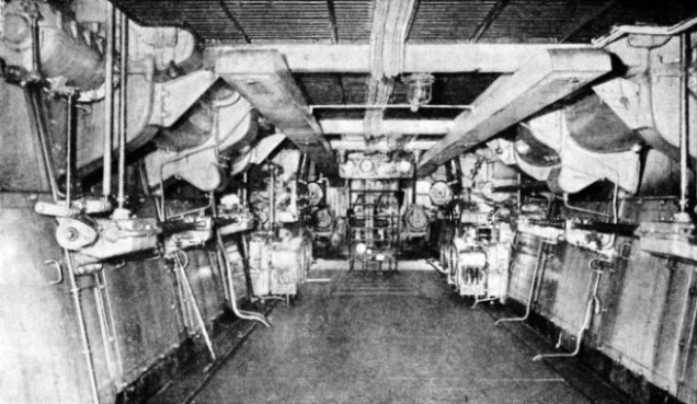
A MOTORSHIP’S ENGINE-ROOM is spacious, clean and comparatively simple in lay-out. This photograph shows the control position in the engine-room of the Italian liner Vulcania, one of the world’s largest motorships. Her sixteen-cylinder four-stroke double-acting engines have a horse-power of more than 26,000 The Vulcania 23,970 tons gross, was built in 1928 and is registered at Trieste.
THE steam engine has served at sea for more than a century and a half. It was harnessed to screw and paddle wheel long before the coming of railways and for generations past has driven ships of all kinds on lake, river and the open sea.
Supreme on every ocean throughout an age, the steam-powered vessel, with mighty pounding piston engine or deep-humming turbine, has made and held its place as bearer of the world’s sea-borne commerce. Speed record breakers, luxury palaces in the world’s pleasant places, carriers of grain and meat, troopers of men to their wars, fighting fortresses in history’s greatest naval fights — all these roles and more have fallen to the steamship in the course of an honourable career. But a rival has arisen — the motorship — with many advantages over the steamer. With lower running costs, the motor-driven vessel offers more cargo space for her tonnage than does the steamship. For fast passenger liners such as the Empress of Britain and the Queen Mary, the smooth-running turbine is still the engineer’s choice. Since 1930, however, the tonnage of motor vessels under construction has exceeded that of steamships on the stocks during any given period. Figures published by Lloyd’s Register of Shipping provide a striking indication of the motorship’s development in recent years. From 1910 to August 1914. some 300 motor vessels were built, totalling 230,000 tons gross. The war of 1914-18 retarded progress in this direction, but since 1919 the building of motorships has gone on apace. In 1934 there were nearly 5,000 of these vessels in the world’s merchant navies, with a total gross tonnage of over 10,000,000.
Nearly all large modern ships now use oil fuel. In the steamer the oil is burnt in the furnaces of boilers that supply steam to turbines or reciprocating engines. In the motorship, however, the oil is burnt directly in the engine cylinders. Although brought to a high state of efficiency in recent years, the internal combustion engine was suggested at an early date. In the seventeenth century engines were devised that depended on the explosion of a charge of gunpowder for their operation. The explosion did not, however, perform any work. The bulk of the gases in the working cylinder escaped into the atmosphere and the remainder, on cooling, produced a partial vacuum. The pressure of the air then forced a piston along the cylinder in the same way as in the atmospheric engines of Watt, Symington and other pioneers of the steam engine.
Among early internal combustion engines working on the “atmospheric” principle was the vacuum gas-engine patented by Samuel Brown in 1823. In this engine a jet of hydrogen gas was burnt below the piston to produce the necessary partial vacuum. The idea was tried on the River Thames in 1827, and the engine drove a boat 36 feet long at a speed of about 7 miles an hour. To those who have read Sir Max Pemberton’s story The Iron Pirate, the use of hydrogen for driving a ship will hold an added note of interest. In the story the pirate warship was driven by hydrogen gas-engines, the gas having been produced by passing steam through special furnaces to remove the oxygen and leave pure hydrogen as fuel.
An internal combustion engine of the direct-acting type, in which fuel was burnt in an enclosed space and the expanding gases provided the power, was introduced by Sir George Cayley as early as 1807.
In 1834 a hot-air engine was designed by John Ericsson. This was not strictly an internal combustion engine, because the cylinder was heated by a furnace below it, but the working principles were similar to those of Cayley’s engine. Some of Ericsson’s engines were used for ship propulsion about 1850 but, with their 14-feet diameter cylinders, they were too heavy in proportion to their power for marine use.
The first successful internal combustion engine was J. J. E. Lenoir’s gas engine, patented in 1860. This was for land use, so that the motorship, in common with the steamer, owes its existence to the experiments of engineers on shore.
In Lenoir’s engine, air and gas were drawn into the cylinder during the first half of the piston stroke. The mixture was then exploded electrically and the expanding gases drove the piston for the remainder of its stroke. This was repeated at the opposite side of the piston on the return stroke, thus producing a double acting engine.
In 1862 a type of engine was proposed by A. Beau de Rochos, in which the mixture of gas and air was to be compressed in the cylinder before ignition. The compression of the explosive charge permits of a larger proportion of air in the mixture, a less noisy explosion is obtained and the pressure of the expanding gases is better maintained during the working stroke.
The use of compression marks the most important stage in the development of the internal combustion engine and is the all-important factor in the working of modern oil engines.
Dr. N. A. Otto produced a gas engine employing compression in 1876, and the cycle of operations is known as the “Otto” cycle. The first stroke of the piston draws in a mixture of gas and air through valves in the cylinder head. During the second, or return, stroke of the piston the air-gas mixture is compressed, and at the end of the stroke the charge is ignited by an electric spark or heated tube.
Then follows the third or working stroke with the expanding gases forcing the piston along the cylinder. During the fourth stroke the products of combustion are expelled through an exhaust valve and the cycle then begins again.
The “Otto” cycle, with one working stroke in four, governs the operation of most internal combustion engines, but there is also a different cycle, known as the “two-stroke”, on which depends the action of another large class of these engines. The two-stroke cycle has one working stroke in two — that is to say, every other stroke is a power-stroke. In both the four-stroke and the two-stroke cycle the pressure is deemed to be applied to one side of the piston only, for the purpose of counting the number of strokes. In practice four- and two-stroke engines can be built to operate as single-acting or as double-acting engines, with the application of power on either, side of the pistons alternately.
Experimental Gas Engines
The two-stroke engine in its original form was introduced by Sir Dugald Clark in 1881. This was a gas engine, and a special pump was provided to charge the cylinder. The only strokes were those for compression and working.
Gas engines have made little progress for ship propulsion, although in the period 1905-10 several experiments were carried out with special gas-producing furnaces that supplied fuel to the machinery.
A TWO-STROKE DIESEL used for marine purposes was adapted from an engine patented by H. F. Fullagar and developed in 1913-14. The sectional model shows how the Fullagar engine worked on the Junkers principle, with two pistons working in either of the two cylinders, but in opposite directions.
One of the earliest internal combustion engines that achieved success for marine use was the Priestman oil-engine. This was a two-cylinder single-acting engine that was fitted in a 28-feet boat in 1888. The fuel used was petroleum or paraffin oil. A special feature of the engine was a vaporizing chamber adjoining the cylinders, and kept hot by a jacket through which passed the exhaust gases. Oil and air under pressure were sprayed into the vaporizer, and the heated charge was drawn into the cylinder on the suction stroke of the piston. The engine worked on the four-stroke principle and was equipped with electric ignition.
The ignition systems used in internal combustion engines may be divided into three classes. First is the electric ignition system, in which a spark is produced in the cylinder by an induction coil and battery or by a magneto. Small petrol-engined launches and fast racing craft are generally equipped with electric ignition.
The next system is that known as the hot-tube system. Part of the explosive charge is forced into a tube, closed at the outer end, attached to the cylinder head. The tube is heated externally on starting and is then maintained at a high temperature by the explosions in the cylinder.
The third ignition system depends for its operation on the heat generated when air, or any other gas, is compressed. This is the most important method of providing ignition, and it governs the action of the diesel engine, the most widely used of marine engines.
The next step forward in the development of the internal combustion engine was the introduction of the “hot bulb” type by Akroyd Stuart in 1890. In this engine the cylinder head is provided with a hollow rounded projection or “bulb”, the interior of which communicates with the bore through a narrow neck. On the suction stroke of the piston a charge of air was drawn into the cylinder through a spring-loaded valve. The next stroke compressed the air, forcing it into the bulb, which was heated by an external blow-lamp.
The “Hot-Bulb” Engine
At the end of the compression stroke a small quantity of oil was sprayed into the interior of the bulb, where it immediately vaporized and ignited. The expanding gases of combustion then drove forward the piston on its working stroke. The blow-lamp was required only on starting, as with the “hot-tube” engine. The “hot-tube”, however, ignites a compressed mixture of oil-gas and air. In the “ hot-bulb ” engine only the air is compressed and the oil, sprayed in at the right moment, is ignited immediately by the heat of the bulb combined with that generated by compression.
The original Akroyd Stuart engine worked on the four-stroke principle, but engines of the “hot-bulb” type, now known as semi-diesels, are used extensively for marine purposes operating with a two-stroke cycle. In a two-stroke semi-diesel engine the air charge is compressed to a pressure of about 200 lb. or more. Fuel injection and the working stroke follow as in the four-stroke engine, but before reaching the end of the working stroke the piston uncovers the exhaust ports. These are rectangular holes in the cylinder walls.
The piston itself serves as a valve to these ports and, as there are no valves, except the fuel injector, in the cylinder head, the two-stroke engine is often referred to as “valveless”. Further movement of the piston uncovers another set of holes or “scavenge” ports in the cylinder connected by a pipe with the engine’s crankcase. The air compressed in the crankcase by the downward stroke of the piston then rushes through the scavenge ports and meets a deflector on top of the piston. The resultant “cyclone” expels the burnt gases through the exhaust ports.
The exhaust pipe leads to a silencer, which, to stifle the deafening roars of a modern diesel installation, attains to large proportions and is often housed in a dummy funnel.
In the two-stroke engine, air is drawn into the crankcase through non-return valves, during the up or scavenging stroke of the piston. Sometimes, however, scavenging valves are placed in the cylinder head and scavenging ports are dispensed with. At the end of the working stroke, air from a separate supply is admitted to the cylinder, the exhaust gases are expelled and the fresh charge is ready for compression on the upstroke of the piston.
An interesting device for starting semi-diesel engines was patented by P. W. Petter in 1922-23. The cylinder head is provided with a metal holder into which is inserted an inflammable cartridge. The lighted cartridge supplies enough heat to start the engine and to run it until the cylinder explosions provide the correct working temperature for the vaporizer.
OPPOSED PISTON DIESEL ENGINE, of about 1,800 horse-power, built by W. Doxford and Sons, of Sunderland, Co. Durham. This engine is a three-cylinder diesel of the two-stroke cycle type developed from the Doxford engine introduced in 1910. Engines of this type are becoming increasingly popular in small cargo vessels and tramp steamers.
Of outstanding importance was the invention of Dr. R. Diesel, who unfortunately did not live to see the vast developments that were to crown his genius. The diesel engine, named after its inventor, was introduced in 1893. For marine purposes the diesel engine is of the four-cycle or two-cycle type, either single- or double-acting. As with the semi-diesel, the oil fuel is sprayed into the cylinder at the end of the compression stroke, but a much higher degree of compression is used. The air in the cylinder is pressed to about 500 lb. and has a temperature of 1,100 degrees Fahrenheit.
The fuel, a small quantity of heavy oil, as soon as it is injected into the cylinder begins to burn (it does not explode) and continues to do so until the supply is cut off, usually when the piston has travelled about one-tenth of the stroke. After the oil has been cut off the gases in the cylinder continue to expand for the remainder of the working stroke. There are two methods of introducing
the fuel into the cylinder. In the true diesel the oil is sprayed in by an air blast from a separate compressor working at a pressure of about 800 to 1,000 lb. The other method is the “solid” or airless injection, where the fuel is forced into the cylinder by special pumps working at a pressure of 5,000 lb. Increasing use is now being made of the second of these injection methods.
The modern marine diesel comprises a number of cylinders in line, all water-jacketed for cooling purposes. Diesel engines of the double-acting type are provided with guides and crossheads to which are attached the connecting rods as in a reciprocating steam engine. An interesting feature in some double acting four-cycle diesels is the use of a lower pressure for the air on the under side of the piston than for that on the top. A combustion chamber, with a narrow communication passage, is attached to the lower side of the cylinder and in this chamber are placed the valves.
Rapid starting is obtained in some types of double-acting diesels by the admission of compressed air to the lower part of the cylinder and fuel oil to the upper part. All large diesel engines are started by compressed air stored in bottles, or steel cylinders.
A diesel cylinder head is provided with four valves — air-inlet, exhaust, fuel injection valve and starting valve for compressed air. The engine is started by engaging the starting and exhaust valves with a camshaft driven from the main crankshaft. After a few revolutions the starting valve is cut out, and the other three valves are brought into operation to run the engine normally on fuel oil.
In contrast to the motor-car engine, the marine diesel is reversible without the use of gears. Reversal is effected by the use of duplicate valve-operating cams on the camshaft. One set of cams enables the ship to be driven ahead; the other set provides for going astern.
First Ocean-Going Motor Vessel
The earliest motorships were four Russian oil tankers built for service on the Caspian Sea in 1908-10. The first ocean-going motor vessel was the Vulcanus, a petroleum carrier of 2,000 tons displacement, built in 1910 at Amsterdam. Her engine was a single-acting six-cylinder Werkspoor diesel, with cylinders of 16-in. diameter and a stroke of 24 in. The engine was reversible and at 180 revolutions a minute developed 500 brake horsepower. On her trials this vessel proved satisfactory, and she was particularly economical in fuel consumption.
In 1911 two much larger motorships were built for the East Asiatic Company of Denmark. One was the Selandia, built at Copenhagen, and the other the Jutlandia, built on the Clyde by Barclay Curie and Company. These vessels, of 4,900 tons gross, were equipped with two eight-cylinder four-stroke engines of 2,500 horse-power. The engines were built by Burmeister and Wain of Copenhagen.
BUILT FOR SMALL GERMAN SUBMARINES by the Maschinenfabrik Augsburg-Nurnberg (M.A.N.) during the war of 1914-18, this type of diesel worked on the four-stroke cycle and had six single-acting cylinders. Only two cylinders are shown in the photograph, and one is cut away to show the piston and cylinder head, with its valves. Engines of this type had an output of 300 brake horse-power at 450 revolutions a minute.
Three more motorships, the Arum, Arabis and Abelia, were built by Swan, Hunter and Wigham Richardson, and Sir W. G. Armstrong, Whitworth and Company for the Flower Motor Ship Company, founded in 1912. These three motorships were twin-screw vessels equipped with two four-cylinder Polar diesel engines working on the two-stroke principle. At 123 revolutions a minute either engine developed 675 brake horsepower. Unfortunately these ships, which had proved highly successful, were lost at sea during the war of 1914-18.
An interesting diesel engine may be inspected at the Science Museum at South Kensington. This engine is of the type built during the war of 1914-18 by the Maschinenfabrik Augsburg-Nurnberg (M.A.N.) for service in small German submarines. The engine worked on the four-stroke cycle and had six single-acting cylinders. Two cylinders only are exhibited and one is cut away to show the piston and cylinder head, with its valves. The cylinders are approximately 10¼ in. diameter with a stroke of 14 in. At 450 revolutions a minute the output was 300 brake horse-power.
The engine was used also for charging accumulators to supply current to electric propulsion motors when submerged. These motors were used also for manoeuvring on the surface, as this diesel engine was not provided with reversing arrangements.
Similar to this engine, but larger, were those fitted in ordinary German U-boats. These engines were of 1,200 brake horse-power, but in the U 135 and U 139 classes of submarine the engines were of 1,750 brake horse-power. Even larger engines of 3,000 brake horsepower were built for installation in the largest, the U 142 class submarines, but these were not in service before the Armistice of 1918.
In 1908 a new type of internal combustion engine, applicable to diesel working, was patented by H. Junkers. In this engine two pistons worked in one cylinder, but in opposite directions, so that the reciprocating masses were balanced. The fuel was admitted in the middle of the cylinder between the pistons, thus eliminating the use of cylinder heads subjected to high temperatures. A model of the engine patented by H. F. Fullagar is preserved in the Science Museum at South Kensington. The Fullagar engine, which works on the Junkers principle, was developed during 1913-14, and in the period 1916-20 was adapted as a two-stroke diesel for marine purposes.
The engine comprises two adjacent open-ended cylinders, either fitted with two pistons. The lower pistons act directly on the crankshaft by connecting rods and crossheads. The crossheads of the upper pistons, however, are cross-connected to the lower piston crossheads by oblique rods.
High Thermal Efficiency
The cranks are set at an angle of 180 degrees and, when the forward lower piston is thrusting downwards, the forward upper piston is pulling up the after crank by the oblique rod. Similarly the after pistons act on both cranks and consequently an ever-turning movement is obtained.
Another two-stroke opposed-piston engine is the Doxford engine, introduced in 1910. In this engine the lower piston drives a crank directly below it. The upper piston carries a cross-piece from which guided connecting rods descend to a pair of outside cranks. An interesting development of the diesel engine is due to the work of W. J. Still from about 1900. In the Still engine the exhaust gases of the diesel engine are used to heat water in a boiler, the feed for which is supplied through the cooling jacket of the cylinder. Steam from the boiler is used in the cylinder on the opposite side of the piston to that taking the thrust of the diesel working stroke. The Still engine was successfully tried in the ship Dolius.
The diesel engine is not only economical on fuel but also its thermal efficiency is as high as 33 per cent, compared with the 28 per cent of the steam turbine and about 17 per cent of the steam reciprocating engine.
In addition to its increasing use in cargo vessels, many large passenger liners have been equipped with diesel engines. The Augustus, an Italian quadruple-screw liner, was built in 1927 for the South American service. She is one of the largest motor vessels built and has a gross tonnage of 30,418. The machinery comprises four double-acting two-stroke six-cylinder M.A.N. engines. They develop a total of 25,000 horse-power at 120 revolutions a minute and give a speed of 19 knots.
THE STARBOARD ENGINE of one of the world’s largest motorships, the Britannic. The engineers standing in the foreground and on the platforms indicate the great size of the powerful engine, which is of the four-stroke cycle double-acting type with ten cylinders. The Britannic’s engines, of the Burmeister and Wain type, were built by Harland and Wolff, Ltd., of Belfast.


 Gas engines have made little progress for ship propulsion, although in the period 1905-
")
