In this chapter the development of steam turbine engines is traced from the earliest known type to the modern geared turbines that propel the great ocean liners of to-day
MARINE ENGINES AND THEIR STORY - 7

ON THE TEST BED at the works of the builders is a set of turbines under construction for a cross-Channel steamer. The photograph was taken at the Wallsend-on-Tyne works of the Parsons Marine Steam Turbine Co, Ltd. The covers have been removed to show the rotor of the high-pressure turbine in the foreground. In the background is the low-pressure rotor of the turbine.
THE principle of the steam turbines that drive the 80,000-tons RMS Queen Mary at a speed of over thirty knots was discovered 2,000 years ago. For more than a century the steam engine has served mankind as a reciprocating machine in which a piston is driven backwards and forwards by steam pressure in a cylinder. The piston rod is attached to one end of a connecting rod which turns a crank and so moves the wheels of a locomotive or factory engine, or the screw propeller of a ship.
Reciprocating engines, however, have their limitations. Efforts have been made from time to time to dispense with the backward and forward movement of heavy masses of metal and so permit of greater speed. Rotary steam engines of various types have been invented, but in most of them the action is partly reciprocating, and none of them has survived in a practical form.
The first rotary steam engine was invented by Hero of Alexandria about the year A.D. 50. The machine worked on the principle of “reaction” which was to be re-adopted nineteen centuries later for the driving of the largest ships in history. Three hundred years ago another type of turbine, working on the “impulse” principle, was invented by Giovanni Branca. Modern turbines are of either type, but generally they combine both of the principles involved and are known as impulse or impulse reaction turbines. Hero’s engine consisted of a hollow ball mounted so that it could revolve on two pivots, one of which was hollow, leading down to a cauldron of water below. The ball was provided with two hollow “spokes” on opposite sides, with the ends, or nozzles, bent at right angles - swastika fashion. A fire was lit and the steam from the cauldron rushed up the pivot pipe into the hollow ball and out of the bent nozzles. The pressure on the portions of the nozzles opposite the orifices was unbalanced and drove the “spokes” and ball round in a direction contrary to that in which the steam issued. This is the physical effect known as “reaction”, and it may be further illustrated by considering the recoil of a gun. When a gun is fired it is driven backwards by a force equal to that which drives out the bullet or shell.
In Giovanni Branca’s engine (1629) a jet of steam impinged on vanes attached to the rim of a horizontal wheel that was “blown” round in much the same manner as a windmill. Branca’s engine may be regarded as the first impulse turbine. For practical purposes, however, the first turbines were worked by water. This type, similar to the familiar water-wheel, grew in favour from the beginning of the nineteenth century and now, in suitably modified form, reigns supreme in the world’s largest hydro-electric power stations.
It is to the genius of the Hon. Sir Charles A. Parsons that we owe the development of the modern steam turbine. In 1884 Sir Charles Parsons patented a reaction turbine consisting of a drum or rotor fitted with a series of rows of blades, inclined at angles of about 45 degrees. Between each row of blades are others inclined in the opposite direction and attached to the inside of the casing surrounding the rotor. The first fixed row of blades serves as a series of nozzles from which the steam issues and impinges on the first row of moving blades, driving them forward and so turning the drum.

ORIGINATOR OF THE MODERN TURBINE, the Hon. Sir Charles A. Parsons was born on June 13, 1854. In 1884 he patented a reaction turbine consisting of a bladed rotor revolving in a casing fitted with fixed blades. He lived to see steam turbines propelling most great modern ships all over the world and died on February 11, 1931.
In the Parsons turbine, however, this impulse action is not the main driving force. The rotor blades are so shaped that they discharge the steam with considerable velocity, so that the rotor is driven round mainly by reaction. It is on this impulse-reaction principle that the modern liner’s turbines work.
Two rows of blades, fixed and moving, would have been insufficient to use fully the energy of the steam. For this reason the Parsons turbine employs a number of blade rows in series, allowing for the reasonable expansive working of the steam. The original Parsons turbine of 1884 is now exhibited in the Science Museum at South Kensington. It was not used for marine purposes but, running at 18,000 revolutions a minute, it was used for driving a dynamo - forerunner of the giant turbo-generators of modem electric generating stations where steam is the source of power.
Two features of this turbine are important. The steam entered the casing at the centre and passed outwards through the fixed and moving blades. The object was to avoid end-thrust.
First Used on Land
In most modern turbines the difficulty is overcome by using “dummy pistons”, or large circular disks on which the steam presses to counteract the side pressure of steam on the moving blades. The second important point is that the 1884 machine is of the parallel-flow type. Here the steam flows in a direction parallel to the axis of the rotor. Alternatively a turbine may be of the radial-flow type, in which the steam passes radially outwards from the axis of the rotor.
The mechanical advantages of the steam turbine for ship propulsion were realized from the outset. Turbines are lighter, perfectly balanced, yield greater speeds and occupy less space, power for power, than reciprocating engines. For naval use they conform to the early ideal of having the engine below the water-line. There are no heat losses due to alternate cooling and heating of the working components and there is no need for internal lubrication.
The first turbines were employed for generating electric light on land, and they exhausted direct into the atmosphere without the use of a condenser. By 1892 turbines had begun to be used with condensers and proved, in certain conditions, to be more economical in coal consumption than reciprocating engines.
Among the early troubles that were experienced by the first turbine engineers was that relative to propellers. Once again models of ships and screws were employed to solve the problems of propulsion, just as they assisted Smith and Ericsson in their propeller experiments described in the chapter “The Development of the Screw Propeller”.
Propeller efficiency and hull resistance were determined by testing a series of models, from 2 to 6 feet long. These were towed in a tank by falling weights or were self-propelled by twisted strands of rubber through gearing. When they were self-propelled, the propeller torque (or driving twist) was measured by a dynamometer on the shaft. Such experiments were necessary because the turbine runs at a far greater speed than the reciprocating engine and the problem of choosing the most suitable hull and propeller required considerable thought and investigation.

THE ORIGINAL TURBINE ENGINE of the steamship Turbinia, built in 1894 at Wallsend-on-Tyne. She was a vessel with a displacement of 44½ tons, and was 100 feet long, with a beam of 9 feet and a draught of 3 feet. The turbine, built by C. A. Parsons & Co, is of the radial-flow type and comprises a series of fixed and rotary disks fitted with rings of blades. It is now in the Science Museum, South Kensington.
From these experiments sprang the famous Turbinia. Her engines and the after part of her hull are now preserved in the Science Museum, South Kensington. The Marine Steam Turbine Company, Ltd, was formed for the purpose of building this experimental vessel, and she was built in 1894 in a small yard at Wallsend-on-Tyne. She was 100 feet long, 9 feet in beam and 3 feet in draught, with a displacement of only 44½ tons. The original turbine and the boilers were built by C. A. Parsons and Co, at its Heaton works, New-castle-on-Tyne.
The turbine drove one propeller shaft and was of the radial-flow type instead of the parallel-flow pattern that was subject of Sir Charles Parsons patent. The choice of the less efficient type of turbine was due to temporary legal difficulties that arose in connexion with Sir Charles’s patents.
This turbine also is preserved in the Science Museum and comprises a series of fixed and rotating disks, each fitted with rings of blades. Steam, flowing outwards from the axis of the rotor, passed alternately between the fixed and moving blades. Then, flowing inwards behind a moving disk, it again passed outwards between the next pair of disks, with their alternate rings of fixed and moving blades. Steam was supplied to the inner portions of the disks through holes near the rotor shaft. For reversing purposes the rim of the last disk was provided with blades driven by jets of steam.
Despite careful experiments, however, the Turbinia’s first efforts were disappointing. She was designed to break all speed records then existing, but her greatest speed, even with a number of propellers on her single shaft, was only 19¾ knots. Investigations were then made to determine the cause of the failure.
Nine Propellers on Three Shafts
In the shafting between the turbine and the propeller there was introduced a specially made torsion-meter - an instrument that enables the twist of a shaft to be measured when under load. The output of the turbine was found to be in full agreement with the estimated horse-power.
The fault therefore lay with the propellers. The screw shaft ran at between 1,600 and 2,000 revolutions a minute, and it was observed that at this speed the propeller formed cavities in the water and so absorbed a large amount of the engine’s power uselessly. With wide-bladed propellers placed tandem on the shaft better results were obtained, but the speed still fell short
of that required. In 1896 the original turbine was removed and replaced by three parallel-flow Parsons turbines, driving separate shafts.
These turbines were of approximately equal power. The high-pressure turbine on the starboard side took steam directly from the boiler. The steam exhausted into an intermediate-pressure turbine on the port side of the vessel. The intermediate-pressure turbine exhausted into a low-pressure turbine that drove the central shaft. This turbine exhausted into the surface condensers.
Steam was generated at a pressure of 210 lb by a Yarrow type water-tube boiler, modified to the specification of Sir Charles Parsons. The pressure was reduced at the engines to 150 lb and expanded in working to an absolute pressure of 1 lb before exhausting to the condenser. This expansive working is similar in principle to the multi-stage expansion of reciprocating engines. Instead of using pistons and cylinders of increasing size, the turbine is provided with progressively larger blades to enable the steam to deliver its mechanical energy by working expansively.
Each turbine comprises a light steel rotor or drum fitted with blades resembling closely-set spokes. These bladed “wheels” are spaced approximately a blade-width apart and are arranged in series. Each series contains blades of larger size than those in the preceding series, to provide for the expansion referred to above. Between every row of rotor blades is a row (or ring) of fixed blades attached to the outer casing.

THREE-SHAFT ARRANGEMENT of Parsons steam turbines was in use before reduction gearing was introduced. The high-pressure turbine drove the centre propeller shaft and the low-pressure turbines drove the two wing shafts. Similar turbines, installed in 1901 in the King Edward, a Clyde passenger steamer, had an estimated horse-power of 3,500 and drove her at a speed of 20½ knots on trials.
Steam enters the high-pressure end of the turbine, where the smaller blades are, and rushes along the annular space between the drum and the casing. Acting by impulse and reaction on the moving blades, and governed by the fixed blades, the steam thus drives the rotor at high speed, finally exhausting into the condensers. On board the Turbinia the condensers were cooled by water from scoops fitted to the outside of the hull and these were capable of reversal to clear any obstructions in the condenser tubes. A pump was used to circulate the water when the vessel was starting or at rest.
The engines of the Turbinia developed about 2,000 shaft horse-power, and there were nine propellers, three on each shaft.
In June 1897 the Royal Navy celebrated the Diamond Jubilee of Queen Victoria by the holding of a review at Spithead. Before the eyes of Britain’s fleets, the Turbinia made an unofficial and spectacular display - at a speed of 34½ knots.
The sensational performance of the Turbinia drew the attention of the Admiralty to the possibilities of the steam turbine for naval use, especially for high-speed torpedo-boat destroyers. The first British destroyer to be driven by turbine engines was HMS Viper, built by Hawthorn, Leslie and Co. in 1899. HMS Cobra, a sister ship of HMS Viper, was also fitted with turbines. The engines were made by the Parsons Marine Steam Turbine Company, and were similar to those of the Turbinia.
Four propeller shafts were used in either vessel and there were separate sets of engines, on either side of the vessel, each comprising a high- and a low-pressure turbine. Two screws were originally used on each shaft, but later HMS Cobra’s shafts were each fitted with three propellers.
HMS Viper, with a displacement of 370 tons, was the first of the two vessels to undergo trials, and her mean speed on a one-hour’s trial was over 36½ knots, with a maximum speed of just over 37 knots over a measured mile.
The application of turbines to the propulsion of merchant vessels was not long in following. In 1901 a Clyde passenger steamer of 650 tons, the King Edward, was built by W. Denny and Brothers, of Dumbarton, and engined by Parsons.
The King Edward had three propeller shafts. The centre shaft was driven by a high-pressure turbine supplied with steam at a pressure of 150 lb. The central turbine exhausted into two low-pressure turbines driving the wing shafts. Originally these wing shafts carried two propellers each, but later a single screw was used on each shaft. Reversing turbines were built into the exhaust casings of the low-pressure turbines and to either of these machines, whether for working ahead or astern, high-pressure steam could be admitted for manoeuvring purposes. In these circumstances the central shaft was idle.
Early Turbine Successes
A fine model representing a three-shaft arrangement similar to that of the King Edward is preserved in the Science Museum at South Kensington. The valves controlling the steam supply on the system outlined above are shown in the model and the surface condensers are shown to port and starboard of the low-pressure wing turbines.
During trials held in June 1901 the King Edward attained an average speed of 20½ knots. The estimated indicated horse-power of the engines was 3,500.
The vessel gave a better performance than could have been expected had she been fitted with triple-expansion engines and in 1902 her builders built a second turbine steamer, the Queen Alexandra, with a displacement of 750 tons. Steam was used at 150 lb pressure and her speed averaged 21½ knots on trial, with the central shaft revolving at 750 and wing shafts at 1,090 revolutions a minute. The estimated indicated horse-power was 4,400.
 The success of these turbine steamers led to the building of others for the cross-Channel services. In 1902 W. Denny and Brothers built The Queen for the Dover-Calais route, and in 1903 the Brighton for the service between Newhaven and Dieppe. The Admiralty bought a turbine-driven destroyer, HMS Velox, with machinery similar to that of HM Ships Cobra and Viper.
THE FIRST GEARED STEAM TURBINE for marine use was made in 1897 by Parsons Marine Steam Turbine Co, Ltd, and installed in a twin-screw launch belonging to the yacht Charmian. The turbine, of 10 horse-power, was geared to two propeller shafts by helical spur wheels, with a reduction ratio of 14 to 1.
With the two earlier destroyers it had been found that turbines were more efficient than reciprocating engines at high speeds; but at low speeds the position was reversed. This was before the days of reduction gearing for turbines. To enable HMS Velox to adopt a comparatively low cruising speed economically, she was fitted with two sets of 150 horse-power triple-expansion reciprocating engines, each connected by a detachable coupling with one of the wing turbines.
For cruising at speeds of about 13 knots or less, the main steam supply passed to the reciprocating engines and was then exhausted into the turbines. For higher speeds the steam was taken direct to the turbines and the triple-expansion engines were disconnected.
In 1903 another turbine-driven destroyer, HMS Eden, was built. In this vessel the cruising problem was solved by the provision of auxiliary turbines for use at slow speeds.
In 1906 was built the famous battleship HMS Dreadnought. She was designed for a greater speed than any other battleship. For the first time a great battleship was equipped with Parsons steam turbines and those in HMS Dreadnought, driving four screws without the use of gearing, gave her a speed of over 21 knots. This ship, with her ten 12-in guns and great speed, may be said to have revolutionized naval warfare.
In the Mercantile Marine also the use of turbines progressed from small river steamers and cross-Channel packets to large passenger ships and cargo vessels. The first large steamers to be driven by turbines were the Victorian and the Virginian of the Allan Line, completed in 1905. These transatlantic liners were of 10,635 tons gross and, with a shaft horse-power of 12,000, had a speed of 19 knots. In the same year the Cunard liner Carmania, of 19,524 tons gross, was completed and fitted with turbines driving three shafts. In 1907 the famous Cunarders Lusitania and Mauretania were equipped with turbines driving quadruple screws.
Combination of Two Systems
Even in these large ships the turbines were coupled direct to the propeller shafts; no gearing was used. The problem set by the Turbinia still persisted - how to use the wonderfully efficient turbine to the best possible advantage. Improvements to the steam turbine were made from time to time and details of design were perfected. The use of the steam turbine in vessels at slow speeds, however, required special consideration because, although the screw propeller required a comparatively slow rate of revolution, the turbine had to revolve at a tremendous speed to attain its maximum efficiency. Of the two methods used to overcome the difficulty, one was the combination of reciprocating engines and turbines.
The Otaki, built by W. Denny and Brothers for the New Zealand Shipping Co. in 1908, was the first ship in which this system was used. This ship had three propellers; the two wing shafts were driven by reciprocating engines, both exhausting into the turbine driving the centre shaft. For manoeuvring and going astern, the reciprocating engines only were employed. A special automatic steam valve was used to cut out the turbine and permit the wing engines to exhaust directly into the condensers. This system was subsequently adopted in many large Atlantic vessels, including the White Star liners Olympic and Titanic of 1911.
The second method of transmitting turbine power to the propeller shaft is that now generally adopted - the use of reduction gear-ing. The idea had been tried as early as 1897 in a launch belonging to the yacht Charmian, illustrated on page 663. The 10 horse-power turbine was geared to a pair of propeller shafts by helical spur wheels with a reduction ratio of 14 to 1.
Merchant steamers, including passenger ships, were later fitted with geared turbines and reduction gearing was used for the first time in the British Navy in the twin-screw destroyer Badger. In the war of 1914-18 geared turbines were adopted by the Admiralty as standard in all warships.
The modern geared turbine is a wonderfully efficient and compact power unit. It often comprises high-, intermediate- and low-pressure turbines grouped near a condenser and driving a single helical gear wheel with double rows of teeth. The design of a turbine permits the use of high-pressure steam - 400 lb superheated to 750° F, yielding a great range of expansion with consequent economy in operation.
A 20,000 horse-power Parsons turbine, 13 feet long, will contain only about 3 lb of steam at a given moment. The steam enters the turbine at about 75 miles an hour, and leaves at about 300 miles an hour, travelling the 13 feet of casing and thousands of blades in one-sixteenth of a second.
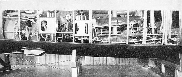
AFTER PORTION of the machinery installed in the Turbinia. The radial-flow type turbines, illustrated here, were replaced in 1896 by three parallel-flow Parsons turbines. The Turbinia had been designed to break all existing speed records, and her speed of 19¾ knots with the original turbines was considered disappointing. With her new engines the Turbinia reached a speed of more than 34 knots at the Royal Naval Jubilee Review at Spithead in June 1897.
You can read more on “The Marine Engineer”, “Progress of the Motorship” and “The Queen Mary’s Engines” on this website.
You can read more on “Steam Turbine Construction” in Wonders of World Engineering


